The CCTV new tower is a remarkable
project in China, even in the world. It is called the representative work of
post-modernism in the history and it is the miracle in the history of building
construction, because of its huge cantilever shape in the air. It is designed
by OMA, and its structural part was design by Arup associated with the East
China Architectural and Design Institute. The total project cost 850 million
euro.
The idea of modeling of this project
with Revit is using the knowledge of mass which we studied in the previous
class and exercised in the previous assignment. The first step is to create a cuboid,
see Fig-1, and set up the base dimension of the building which is 222m*212m*234m
according to the original design solution. Create three parameters in the mass
family and relate these three parameters to the base length and width as well
as the height of the mass separately, see fig-2 and fig-3. So that we can
control the width, length and height of building mass. The next step is to create series of type of mass, void form, to cut the solid
form. Just like you are engraving an sculpture, but using void form instead of
knife(see fig-2). With the ability of space imagination, you will get the final
mass you want(see fig-3).
Fig-1
Original Mass
Fig-2 Using void form of mass
Fig-3 General parameters in building mass
I have tried many ways to use mass of void form to
cut the solid form, like,you can directly draw reference line loops on the
surface of solid form to create void form, using the order of align to align
the suface of void form to the surface of solid form. The idea is quite simple, but undoable,
because when you change the dimension of the building mass, Revit will tell you
over constraints and forbid you to make change. Thus, we can not make
parametric modeling in this way. Revit has kind of limitation that we can not directly
label the dimension on the void form mass, sometimes, we even can not directly
align the surface of void form to other surface. Thus, only by borrowing other
solid form to show the surface of void form, can we snap the surface of void
form. The same method will be used in giving the parameters to void form but
using reference plane.
Considering the above limitation, creating separate
reference plane for drawing the reference loops of void mass and adding
parameters among the reference planes is a good way to realize parametric
modeling, but this parametric property is very limited. For example, when you
make the reference plane of void form to be the place where is the exactly the
reference plane of solid form to be, then the Revit will be confused so that
comes out a window showing “over-constraints”.
It is very easy to cause the scenario of over-constraints
for Revit when trying to use the void mass to cut solid mass and make it
parametric at meantime. Once you got over-constraints, the modeling will lose
the property of parametric, which means you can not change the size of building.
After failed
so many time, I have found a kind of
method which is very efficient in creating new CCTV tower parametric modeling
and has good effect and clear logic.The following steps will tell how I successfully in
makeing the parametric modeling. Following the steps expressed in the second paragraph,
we need to create a few independent families, each of which contains a void
mass, see fig-4. These four families are created to shape the edge of original
building mass.
 Fig-4 Creating four mass families to shape edge
Next, we need to create a mass that could make a
void space in the middle of the solid mass, see fig-5a and fig-5b. When you
creating the void mass family, be sure that the direction of coordinate is the
same as the direction in the family which you will put the void mass into, and
create enough parameters which will help you to locate the void mass in the
solid mass family. The connection between the solid mass family and void family
are exactly those parameters, because those parameters are going to use the
value in the solid mass family to find the place to settle. Fig-7 is another example of void mass to engrave, create connection between the solid family and void
Fig-5a Void mass family in the solid mass family
Fig-6 Void mass use the value of solid mass to
re-locate
mass family, relocate in the solid
mass family. In total, we need to created at least six void mass families to
engrave the solid mass. Within the each void mass family, the parameters should
be created accordingly based on the realistic. Each of six void mass families is individual. Here I just take two of them as example.
Fig-7 The whole process of connecting between solid
and void mass family
After we finishing creating the building mass, see
fig-8, the rest steps are quite easy. First we need to create customized
curtain panel in the mass family and create parameters at meantime
so that we can control the shape and material of curtain panel and make it
parametric, see fig-9. Then, We need to divide the surface of mass building into
pieces and give it a appropriate number, following by loading the curtain panel
created before to get the building facade, see fig-10. Also, We can change size
and of material of curtain panel after loaded into the building mass family,
see fig-11,
 Fig-8 Final building mass
Fig-9 Customized curtain panel
because in the previous step we have already made
curtain panel into parametric. There is another method should be pointed out
that after finish creating building mass, we could directly load this building mass
into architectural project, and create curtain
Fig-10 Building facade
Fig-11 Parameters of curtain panel
panel system, roof, floor and so on. However, the curtain system created in this way is not
customized or parametric, see fig-12a and fig-12b.
Fig-12a
Creating curtain panel by Revit
Fig-12b Its
rendering
Once finishing above steps, the building mass would
look like a real building(see fig-13). However, the modeling process is not
over yet so far. We need to load the building mass with curtain panel into
architectural project and to set up floor level under the elevation view for
creating mass floor and roof later. After these steps were done, the modeling
could be called real building modeling. Nevertheless, we still need to design
floor plan for creating building information, like legend and room schedule.
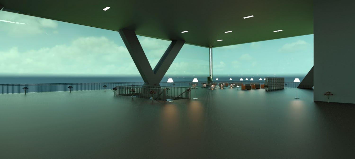
Here, I created different rooms on level 5 as well as furniture, decoration,
stair, elevator, equipment and so on(see fig-14a, fig-14b, fig-14c). And the
building information was created at meantime(see fig-15). In order to make this
project much more vivid and beautiful, toposurface, roads, landscaping and environmental elements
were all added into this project(see fig-13).
Fig-13 Final rendering of preferred option
Fig-14a Interior rendering with furniture
Fig-14b Interior rendering with furniture
Fig-15 Room schedule and legend
In the end, I want to talk about another limitation
of Revit that when we setting the parameter to the mass or drawing the
reference line or surface, the color of each line are the same, which means the
color is either black for dimension or purple/green for reference plane/line.
If we create a lot of dimensions, reference planes or lines, we will be
confused by these in same color. If we can change the color and type of default
line and manage them efficiently, just like what we do when we use AutoCAD, the
working efficiency may be higher.